How to wiring a single phase distribution board?
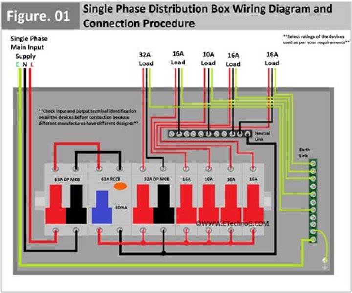
Below is the given wiring diagram of Single Phase Distribution Board with RCD in both NEC and IEC electrical wiring color codes. The same description and detailes can be used as mentioned for the above fig 1. This is the main operating switch which is used to control the electric power supply in the building (s).
How do I connect the szlcd control box to the thermostat?
• Connect the red/white wire routed from the SZLCD thermostat +12VDC terminal to the red/white wire from the SZLCD control relay box. • Connect the orange wire from the SZLCD thermostat COMMS terminal to the orange wire that runs from the SZLCD control relay box.
How to install a Dometic szlcd control box?
Place cover on the thermostat and push until an audible click is heard. h. At the 14 1/4″ x 14 Y4′ opening, connect the following: • Plug the supplied four conductor wire harness that is red/white, orange, black, and red into the SZLCD control relay box. • Connect the +12VDC red supply wire to the red wire from the SZLCD control relay box.
How do you install a gas furnace control center?
INSTALLATION 1. Disconnect wiring from blower control center, noting location. Be sure to remove quick-connect jumper on standing pilot models between Gas 1 and Gas 3 and place on new control center. 2. Remove existing blower control center and install new blower control center in control box. Be sure top edge of board is in the mounting slot.
How to change the configuration of the pellet Control Board?
To change the configuration the control board must be in the off position plugged into a cold stove, (no lights or running components) with the jumper molex removed (see the illustration below). In this condition press and hold the manual auger button down and press both fan up and fan down arrow keys at the same time.
INSTALLATION 1. Disconnect wiring from blower control center, noting location. Be sure to remove quick-connect jumper on standing pilot models between Gas 1 and Gas 3 and place on new control center. 2. Remove existing blower control center and install new blower control center in control box. Be sure top edge of board is in the mounting slot.
Which is the correct wiring diagram for an OT switch?
*OT is a switch that opens when an overtemperature condition exists (Type MFO and MGO only) T1 T3 MOTOR 3 2 L2 T2 L3 T3 T2 L1 1 T1 13 14 43 44 53 54 31 32 21 22 Status (N.O. or N.C.) Location A1 15 B1 B2 16 18 B3 A2 B1 B3 15 Supply voltage 16 18 L M H 2 Levels B2 21 22 13 14 X1 X3 AC L1 L2 LOAD Orange X2 Green AC 1 5 9 2 6 10 4 8 12 13 (–) 14 (+)
Can a schematic diagram show both control and motor?
Schematic diagrams do not always show both control and motor connections. Many schematic diagrams show only the control circuit. Notice in this schematic that there is no complete circuit to M motor starter coil because of the open start push button and open M auxiliary contacts.
Do you need wiring diagram for Mach3 breakout board?
MACH3 TESTED SETTINGS FOR SPINDLE RELAY AND PWM CONTROL. Question: I need wiring diagram from mach3 breakout board to hy inverter. Current Solution. I suppose you are trying to determine how to connect the VFD tothe.
What are the components of a distribution board?
Main Distribution Board or Fuse Boards (Consumer Unit) usually contains on the following three main units to control and distribute electric supply to the different connected appliances and devices through electrical wiring cables and wires. DP = Double Pole MCB (The main isolator or main switch). RCD (Also DP) Residual Current Devices for safety.
What can you do with a wiring diagram?
Let’s go back and have a look at the control panel, and try and figure out some of the connections by following a wiring diagram. As I’ve mentioned in the previous articles, this is a control panel that is used for a system that turns wastewater into clean water.
MACH3 TESTED SETTINGS FOR SPINDLE RELAY AND PWM CONTROL. Question: I need wiring diagram from mach3 breakout board to hy inverter. Current Solution. I suppose you are trying to determine how to connect the VFD tothe.
Do you need wiring diagram for CNC Mach3?
CNC Mach3 – Setup the A slave axis. Question: Need wiring diagram from mach3 USB breakout board to inverter. Current Solution. I suppose you are trying to determine how to connect the VFD.Jan 03, · The relay on the breakout board is a pass-through switch with NO, COM and NC connections.
What kind of wiring is needed for a 5 axis breakout board?
5 Axis Breakout Board Interface Adapter Wiring Diagram for Reference. Compatible with MACH3, Linux CNC (EMC2) etc. parallel-control CNC software. Example wiring of stepper drivers to 5 axis breakout board with Mach3 info. Precision motion control: ODrive Servo?